
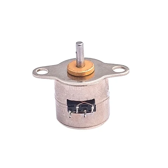
Description
Low price Nema 4 micro stepper motor with metal gear. Rated voltage DC 5V, optional current 0.33A/0.27A/0.128A, corresponding resistance 15Ω/18Ω/39Ω, diameter 10mm, stepping angle 18 degree. 2 phase miniature bipolar stepper motor, wide applications.
Specification Datasheet
| Model | ATO-SM1024 | ATO-SM1051 | ATO-SM1055 |
| Rated Voltage | 5V | 5V | 5V |
| Rated Current | 0.33A | 0.27A | 0.128A |
| Resistance | 15Ω | 18Ω | 39Ω |
| Phase | 2 Phase | 2 Phase | 2 Phase |
| Stepping Angle | 18° | 18° | 18° |
| Excitation Method | 2 | 2 | 2 |
| Pull-in Torque | 0.6 mN-m (500 pps) | 0.32 mN-m (500 pps) | 0.35 mN-m (500 pps) |
| Pull-out Torque | 0.7 mN-m (500 pps) | 0.45 mN-m (500 pps) | 0.45 mN-m (500 pps) |
| Holding Torque | 1.6 mN-m (0 pps) | 1.3 mN-m (0 pps) | 1.3 mN-m (0 pps) |
| Max. Continuous Response Frequency | 1200 pps | 1600 pps | 1200 pps |
| Max. Starting Frequency | 900 pps | 1000 pps | 900 pps |
| Drive Mode | Bipolar Drive | ||
| Ambient Temperature | -10℃~55℃ | ||
| Insulation Resistance | 500VDC 50MΩ min | ||
| Insulation Grade | E |
Phase Sequence Excitation & Dimensions Diagram (Unit: mm)
- 5V 0.33A Micro Stepper Motor (ATO-SM1024)
| Connector PIN Location | ||||||
| PIN No. | Color | CCW←→CW (Seen from flange side) |
Phase | |||
| 1 | – | ON | – | – | ON | A |
| 2 | – | – | – | ON | ON | B |
| 3 | – | – | ON | ON | – | A |
| 4 | – | ON | ON | – | – | B |
- 5V 0.27A Micro Stepper Motor (ATO-SM1051)
| Connector PIN Location | ||||||
| PIN No. | Color | CCW←→CW (Seen from flange side) |
Phase | |||
| 1 | – | ON | – | – | ON | A |
| 2 | – | – | – | ON | ON | B |
| 3 | – | – | ON | ON | – | A |
| 4 | – | ON | ON | – | – | B |
- 5V 0.128A Micro Stepper Motor (ATO-SM1055)
| Connector PIN Location | ||||||
| PIN No. | Color | CCW←→CW (Seen from flange side) |
Phase | |||
| 1 | Brown | – | ON | ON | – | B |
| 2 | Black | ON | – | – | ON | B |
| 3 | White | ON | ON | – | – | A |
| 4 | Red | – | – | ON | ON | A |
Details
Tips: Nema 4 micro stepper structure.
Nema 4 micro stepper is mainly composed of base body, rotor, gear and linear guide.
- The base body also acts as a stator, with magnetic poles, stator teeth, coils and control circuits on its surface.
- The rotor is located above the stator, with mover teeth on the lower surface. The function of guide rail is equivalent to a linear bearing, keeping the rotor in place.
- There is a shell above the guide rail and rotor for sealing. The rotor is separated from the surrounding elements by an air gap.
Reviews
There are no reviews yet.