
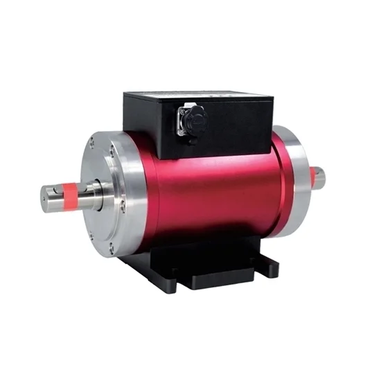
Description
Rotary torque sensors have capacity range from 0.05 Nm, 0.2 Nm, 5 Nm, 20 Nm, 100 Nm, 200 Nm, 300 Nm, 500 Nm, 1000 Nm, 2000 Nm, 5000 Nm, 10000 Nm, 20000 Nm, 50000 Nm to 300000 Nm. Torque sensor capacity can be customized according to customer requirements.
After purchasing one ATO rotary torque sensor, you can buy a special torque meter ATO-DPM-DYN303 to obtain readings directly, or buy a F/I or F/V transmitter in drop-down list to transmit frequency signal to 4-20mA/1-5V signal.
Specification
| Model | ATO-DYN-210 |
| Shipping Weight | 5~1000kg |
| Capacity Range * | 10 Nm ~ 0-300000 Nm (For 150000-300000 Nm capacity, please contact us for a quote.) |
| Accuracy * | ±0.1%FS (for capacity<1000 Nm), ±0.2%FS (for capacity>1000 Nm), ±0.5%F.S (for all capacity) |
| Power Supply * | ±15V DC (≥50mA), 24V DC |
| Output Signal * | 5-15kHz, 4-20mA (add external F/I transmitter), 1-5V (add external F/V transmitter), download transmitter user manual |
| Max. Speed | ≤15000rpm |
| Maximum Torsion angle | 2.60x10rad(0.149°) |
| Speed Range | 0-3000rpm, 0-6000rpm, 0-8000rpm, maximum speed 10000rpm |
| Speed Signal | 120/60/10 pulse/turn (measuring range>10000 Nm, it will reach 180 pulse/turn) |
| Temperature Drift on Zero | 0.01%F.S/10℃ |
| Operating Temperature | -10℃~+50℃ |
| Humidity | 0~85%RH |
| Torsion Constant | 3.85x10Nm/rad |
| Response Time | 1kHz |
| Insulation Resistance | 1000MΩ |
| Inertia Moment | 0.38 Kgcm |
| Stability | 0.3%FS/year |
| Zero Output | ±2%F.S. |
| Safety Overload | 150%F.S |
| Breaking Load | 200%F.S |
| Bridge Voltage | DC 10V |
| Material | Alloy steel |
| Protection Class | IP65 |
| Electrical Connection | circular connector |
| Wiring | Red: +24V; Black: GND; Green: Torque signal; White: RPM signal; Yellow: Shielded wire (can be disconnected) |
| Cable Length | 3m (Φ5mm), or other customizable lengths |
| Ultimate Cable tension | 98N |
Rotary Torque Sensor Dimension (unit: mm)
| Capacity | Dimension (mm) | |||||||||||||||
| Φdj6 | ΦD | A | L | L1 | H | h | E | E1 | B | B1 | C | F | S | Speed (rpm) | C Key size (b*l1*m) | |
| 10, 20, 30, 40, 50, 100 Nm | 18 | 85 | 150 | 224 | 32 | 123 | 58 | 72 | 95 | 62 | 90 | 6.5 | 112 | 10 | 6000 | 6*32*6*1 |
| 200, 300 Nm | 28 | 95 | 152 | 242 | 42 | 133 | 63 | 72 | 95 | 62 | 90 | 6.5 | 121 | 10 | 5000 | 8*42*7*1 |
| 500, 700 Nm | 38 | 105 | 154 | 272 | 56 | 144 | 69 | 72 | 95 | 62 | 90 | 6.5 | 136 | 10 | 4000 | 10*56*8*2 |
| 1000 Nm | 48 | 115 | 156 | 328 | 82 | 150 | 70 | 72 | 95 | 82 | 110 | 8.5 | 165 | 12 | 3000 | 14*82*9*2 |
| 2000, 3000 Nm | 65 | 132 | 165 | 385 | 105 | 172 | 80 | 72 | 95 | 82 | 110 | 8.5 | 192.5 | 12 | 2500 | 18*105*11*2 |
| 5000, 7000 Nm | 75 | 146 | 180 | 396 | 105 | 187 | 89 | 72 | 95 | 82 | 110 | 8.5 | 210 | 12 | 2000 | 20*105*12*2 |
| 10000, 20000 Nm | 100 | 182 | 180 | 447 | 130 | 244 | 122 | 80 | 110 | 112 | 140 | 10.5 | 230 | 15 | 2000 | 28*130*16*2 |
| 50000 Nm | 165 | 250 | 185 | 700 | 240 | 331 | 180 | 120 | 190 | 150 | 190 | 12.5 | 350 | 15 | 1900 | 40*240*22*2 |
| 100000 Nm | 210 | 330 | 200 | 820 | 300 | 410 | 210 | 160 | 200 | 250 | 290 | 12.5 | 410 | 15 | 1700 | 50*300*28*2 |
| 150000 Nm | 235 | 350 | 250 | 900 | 315 | 420 | 220 | 220 | 260 | 250 | 290 | 17 | 450 | 15 | 1200 | 56*315*32*2 |
| 200000 Nm | 255 | 360 | 210 | 900 | 320 | 446 | 140 | 220 | 260 | 250 | 290 | 17 | 450 | 15 | 1100 | 56*320*32*2 |
Rotary Torque Sensor Installation
Details
Diagram of Forces
Tips: How to install a rotary torque sensor?
The steps of torque sensor installation:
- According to the connection form of the shaft and the length of the rotary torque sensor, determine the distance between the prime mover and the load. Adjust the distance between the axes of the prime motor and the load relative to the base level, enable the axes concentricity to be less than Φ0.03 mm. Fix the original motor and load on the base level.
- Install the couplings on the shafts respectively.
- Adjust the distance between the torque sensor and the base level, enable the concentricity of their axis (torque sensor, motor and load) to be less than Φ0.03 mm, and fix the torque sensor on the base level.
- Tighten the coupling and complete the installation.
The requirements of torque sensor installation:
- Power equipment, torque sensor, and load equipment should be installed on a stable foundation to avoid excessive vibration, otherwise, data instability, measurement accuracy reduction, and even damage to the dynamic torque sensor will probably occur.
- Choose the elastic pin coupling or rigid coupling for connection. When the vibration is serious or the concentricity is greater than 0.05mm, it is recommended to use a flexible coupling and install a bearing support at the left and right ends of the torque sensor.
- Adjust the centre height and concentricity of the power equipment, load, and torque sensor separately, which is required to be lower than 0.05mm, and then fix.
Matters needing attention:
- The torque sensor should be installed in an environment where the ambient temperature is 0 ℃ ~ 60 ℃, the relative humidity is less than 90%, and there is no flammable or explosive product.
- It is not suggested to be installed in an environment with strong electromagnetic interference.
Reviews
There are no reviews yet.